The inœnsity the triangldar útributed load at of sectioning is 3333r Referring Fig. Solution Manual - Mechanics Of Materials 7th Edition Gere Goodno - ID5c18dde35afdf.
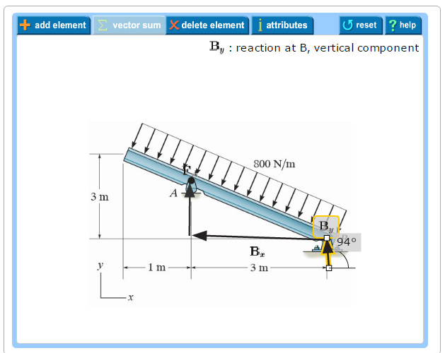
Solved Problem 5 1 Vectors Fa Bx By Part A Draw The Chegg Com
B will be to write the and mcnnent quations.

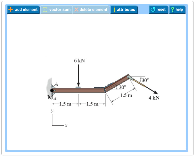
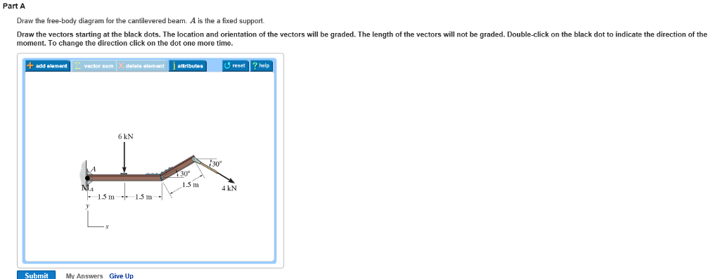
. The cantilevered beam is embedded into a fixed vertical wall at Atext Draw a neat labeled correct free-body diagram of the beam and identify the knowns and the unknowns. Enter the email address you signed up with and well email you a reset link. Therefore the resultant vector for the X-coordinate will be 459 N and for the Y-coordinate will be 314 N.
B o V -300-. Considering the forces to the right of is always zero. SOLUTION Since the loading is discontinuous at the midspan the shear and moment equations must be written for regions and of the beam.
Draw the shear and moment diagram for the beam shown below and clearly label all values of maximum positive and negative shear and moment. Determine the magnitude and direction of the resultant. Ends of a simple beam and at the free end of a cantilevered beam where there can 5.
At point H we have the maximum bending be no resistance to bending the bending moment moment. 5 ft3 ft CB 4 ft A The free-body diagram of the beams right segment sectioned through an arbitrary point shown in Figa will be used to write the shear and moment. 300 1b - diagram of the beams left through an arbitrary shown in fig.
Draw the shear and moment diagrams for the cantilevered beam. 00FMqxd 92908 849 PM Page i An Instructors Solutions Manual to Accompany ISBN-13. Mechanics of materials solution manual.
C 3 a 4 The shear diagram. The free-body diagram of the beams segment sectioned through the arbitrary points within these two regions are shown in Figs. B 1 a 2 Region Fig.
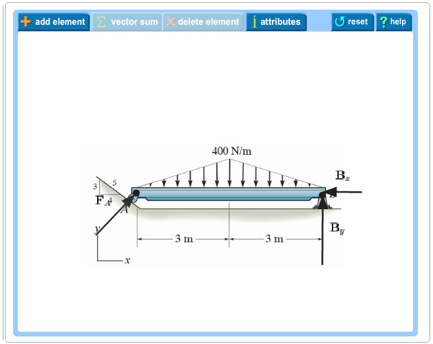
To draw the free body diagram start with a neat rectangle to representing the beam disconnected from its supports then draw and label known force B and. The first step in the solution of a problem should therefore be to draw a free-body diagram. The engine crane is used to support the engine which has a weight of 1200 lbDraw the shear and moment diagrams of the boom ABC when it is in the horizontal position shown.
Solved Problem 5 1 Vectors Fa Bx By Part A Draw The Chegg Com

How To Draw A Free Body Diagram Simply Supported Beam With A Point Load Youtube
Solved Problem 5 1 Vectors Fa Bx By Part A Draw The Chegg Com
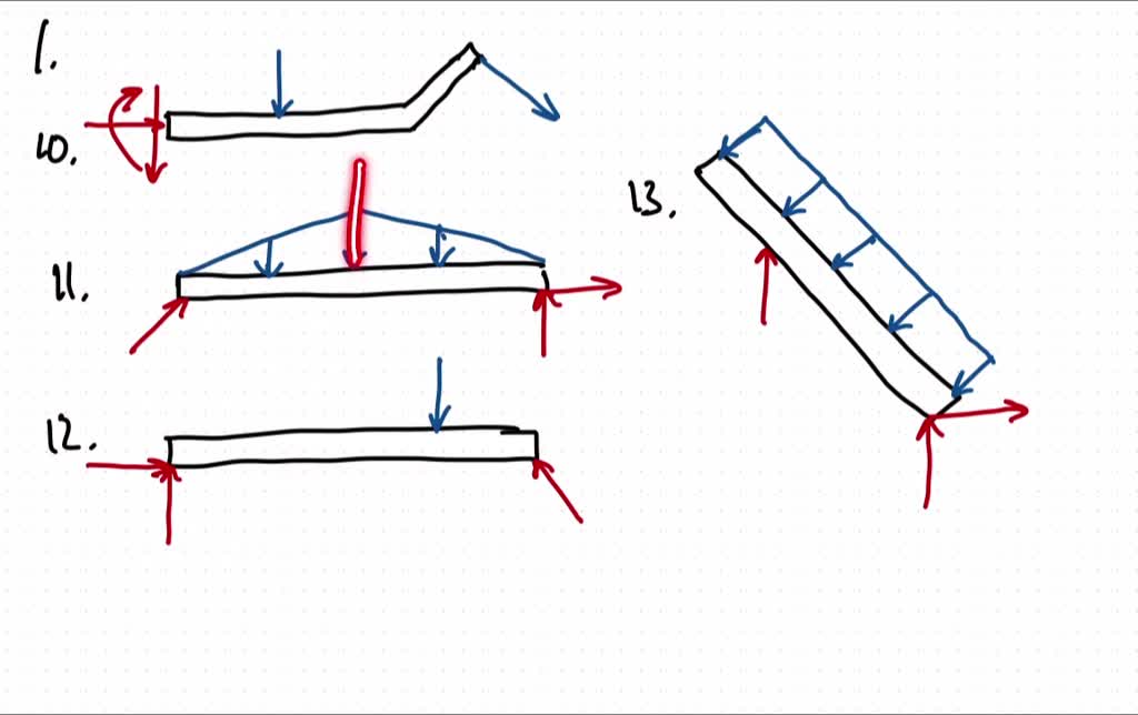
Solved Draw The Free Body Diagram For The Following Problems A The Cantilevered Beam In Prob 5 10 B The Beam In Prob 5 11 C The Beam In Prob 5 12 D The Beam In Prob

Solved 5 1 Draw The Free Body Diagram For The Following Chegg Com
Free Body Diagram Examples Engineering Mechanics Youtube

Shear And Moment Diagrams S B A Invent Nursing Student Tips Civil Engineering Design In This Moment
Solved Part A Draw The Free Body Diagram For The Chegg Com
0 comments
Post a Comment